NOTE: This is a working document that is regularly being edited and added to.
For many years, the Fourier Transform Ion Cycloctron Resonance (FT-ICR) mass analyzer has been one of the most powerful options in terms of mass resolution and mass accuracy. Mass analysis is performed by measuring the frequencies of ion motion inside a magnetic field via "image current" detection.
Basics
The FT-ICR methodology is fundamentally based on ion cyclotron motion, which occurs when ions are placed inside a uniform magnetic field. The force exerted by a magnetic field of strength B on an ion of charge q moving with velocity v is:
Force = q(v × B)
In order to determine the force on the ion, we first take the "cross product" of the velocty and magnetic field vectors (v × B). The "right hand rule" tells us that the cross product will point downward. Now we simply multiply the resulting vector by the ion's charge, q. For a singly charged positive ion, q=1. As such, the force on the positive ion will be directed downward. Conversely, for a singly charged negative ion, q=1, causing the force to be directed upward:
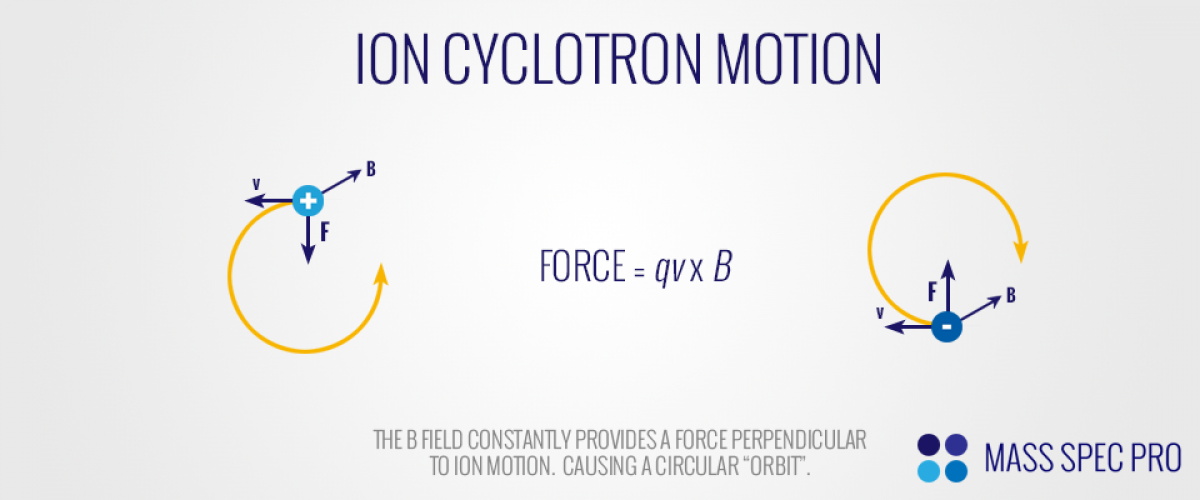
Since the force exerted by the magnetic field is always perpendicular to the ion's velocity, it is perpetually turning the ion. The result is a circular "orbit", with the ion circling round and round until another force acts on it (e.g. a collision with a neutral, an electric field, a change in the magnetic field, etc.). This phenomena of circular ion trajectories in static, uniform magnetic fields has been coined "cyclotron motion", and the frequency of rotation is termed "cyclotron frequency". The cyclotron frequency of an ion is given by:
$$\omega_{cyclotron} = \frac{qB}{m}$$
As is clear from the above equation, the frequency of any ion's rotation only depends on its mass/charge ratio and the magnetic field strength. Conveniently, the ion's velocity does not have any effect. However, the radius of the ion's orbit is dependent on its velocity, as given by:
$$r_{cyclotron} = \frac{mv_{perp}}{qB}$$
where "vperp" is the portion of the ion's velcoty that is in the plane perpendicular to the magnetic field. Some very basic observations can be made based on these relationships. First, heavy ions will orbit with lower frequencies than light ions. Second, heavy ions will orbit with larger radii than light ions, all else being equal. Third, larger magnetic fields induce higher cyclotron frequencies and smaller radii.
Resonant Excitation
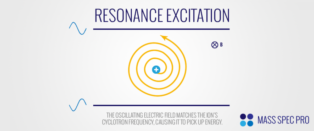
When ions are initially formed or placed in a magnetic field, they are likely to both have realtively small cyclotron radii and are uniformly distributed around the central axis. Both of these characeristics make image current detection difficult, if not impossible. The small cyclotron radii mean that ions do not ever travel closely to surround detection plate, therefore inducing very little image current. Likewise, the random distribution of ions around the central axis means that on average the image current of any one ion will be offset by the image current of an ion on the opposite site of the axis. In order to improve the ability to detect ions within the analyzer, it is desirable to both (1) increase the cyclotron radii of ions to bring them closer to detection plates and (2) makes the ions orbit coherently with one another. Both of these objectives are realized through the use of resonant excitation via electric fields.
Imagine an ion orbiting with cyclotron motion within an electric field, as described above. Now imagine two infinite parallel plates, one above the ion's orbit and another below. Now imagine that each plate has a sinusoidal waveform applied to it, with one plate 180° out of phase from the other. These opposing sine waves generate an oscillating electric field that will accelerate ions toward one plate then the other, back and forth with the frequency of the applied sine wave. If the frequency of the applied electric field is close to the ion's cyclotron frequency, the ion's motion will "resonate" with this electric field. As a result, the ion picks up kinetic energy from the electric field. The increased kinetic energy is observed as an increase in the ion's cyclotron radius:
Basic ICR Cell Geometry
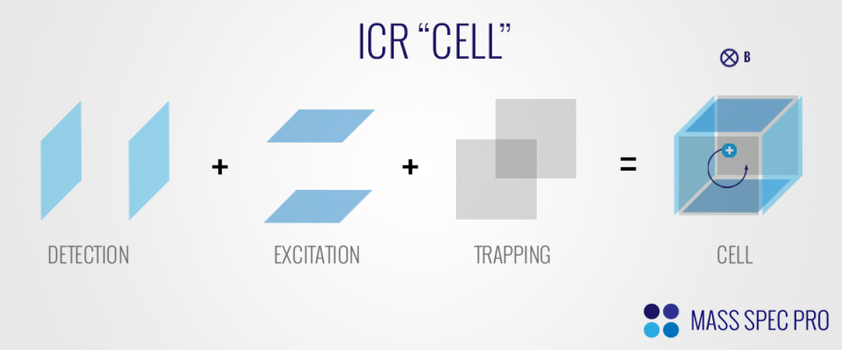
In order to manipulate and detect ions via FT-ICR, ions are confined within a "cell". The ICR cell comprises three pairs of electrodes. The first pair is used to perform image current detection, and the second pair is used to perform resonance excitation. These first two pairs of electrodes are parallel with the magnetic field. The third pair is perpendicular to the magentic field, and is simply used to trap the ions in this axis:
Broadband Resonant Excitation via SWIFT
The above description of resonance excitation only addressed the excitation of a single m/z value through the application of a single frequency sine wave on the excitation electrodes. However, in reality there will be many ions of different m/z in an ICR cell simultaneously. As such, it is desirable to have a method for exciting all m/z values at the same time with uniform strength. This objective is commonly achieved through the use of "Stored Waveform Inverse Fourier Transform" (SWIFT). The SWIFT process starts by determining what m/z range(s) should be excited and then calculating the respective range of cyclotron frequencies for the instrument's magnetic field strengh. It also must be determined what amplitude of excitation is desired across said frequency range. Having determined both the range of frequencies and amplitude for excitation, an inverse Fourier transform is performed to generate a waveform that has the desired properties:
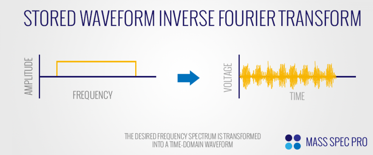
The SWIFT approach is superior to other methodologies (e.g. a frequency sweep) because it is able to provide a unform excitation strength across a wide range of frequencies, meanig that ions across the entire m/z range of interest are excited to the same degree. Since the excitation srength dictates the ions' cyclotron radii, which in turn dictate the strength of the image current detected, the SWIFT approach provides a response that is proportional to ion abundance across the entire m/z range. Other excitation approaches suffer from non-uniformity such that equivalent ion populations at different points along the m/z axis will give different signal strengths due to different excitation strengths (and therefore cyclotron radii).
Image Current Detection
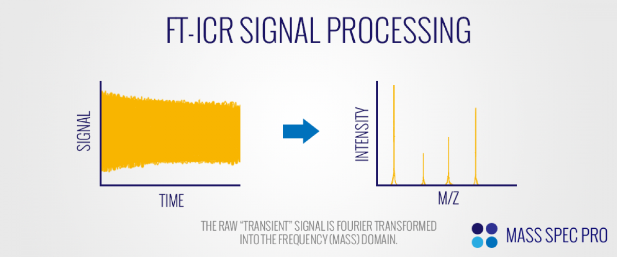
As ions undergo cyclotron motion, they induce sinusoidal "image current" on the detection electrodes. Ions of different m/z values oscillate with different cyclotron frequencies, as explained above. As such, an ion population containing numerous m/z values will simulatneously induce various frequencies of image current on the electrodes. The signal collected by the electrodes is a sum of these various sine waves and is commonly referrered to as a "transient". Although the transient is collected in the time domain, it must be converted to the frequency domain in order to create a mass spectrum. This conversion to the frequency domain is done via Fourier transform (FT):
Since the FT process converts the transient to frequency, which is in turn inversely proportional to m/z, the end result is a mass spectrum. The exact shape of the peaks in the frequency (or m/z) domain depends on some features of the transient itself. For exampe, if the sine waves in time domain have fixed intensities over time (viz. the amplitudes of cyclotron motion remained constant throughout), then the peaks in the frequency (or mass) domain take the shape of a sinc() function. However, if the sine waves decay to near-zero amplitudes during the transient (viz. the intensities of cyclotron motion are damped over time), then the peaks in the frequency (or mass) domain have the shape of a Lorentzian. Either way, there is significant broadening of the peaks at their bases:

In order to minimize the effects of the wide peak bases from the transform process, the transformed signal is often "apodized".
Mass Resolution
If we begin with the equation for cyclotron frequency, ω, and take its derivative with respect to mass, we get:
$$\frac{d\omega}{dm} = \frac{-\omega}{m}$$
Rearrangement of this equation provides:
$$\frac{\omega}{d\omega} = \frac{-m}{dm}$$
This result shows that mass resolution and frequency resolution as directly proportional to each other in FT-ICR. Since we ultimately care about mass resolution (m/dm) as a function of instrumental conditions, we can re-introduce the definition of cyclotron frequency to the above equation and obtain:
$$\frac{m}{dm} = \frac{-qB}{md\omega}$$
Several conclusions can be made from this equation. First, a larger magnetic field will improve mass resolution. Second, for a given ability to resolve frequencies (dω), resolution is inversely proportional to mass. Lastly, if the ability to resolve frequencies improved (smaller dω), mass resolution increases accordingly. It should also be noted that the the Fourier transform process provides both an amplitude and phase angle for each respective frequency. However, the phase portion of the transform is typically not useful in FT-ICR, as the cyclotron frequencies of ions are not phase locked with each other. As such, the ull resolution of the Fourier transform process can not be realized. Instead, it is commonly used in the so-called "magnitude mode", which doesn't have as much frequency resoluton as the normal "absorption mode" (decrease of ~1.75-2.0).