Background
Many modern mass spectrometers create ions at atmospheric pressure (e.g. electrospray) but perform mass analysis of the generated ions under high vacuum conditions. In order to get the ions from source to analyzer, the vacuum chamber is typically broken into three or more vacuum "stages" in which the pressure is gradually stepped down from one chamber to the next. A small hole (aka "conductance limit") separates each stage from the next. As such, the ions must be transmitted through these holes in order to safely arrive at the mass analyzer. The most difficult portion of the ion transfer/focusing is undoubtedly when the ions are first entering the vacuum chamber. As the gas enters the vacuum stage it undergoes a "free jet expansion", spreading out radially and attaining sonic (or even supersonic) speeds. The ions of interest are entrained in this expanding gas beam, but they will ideally be focused back down to a small radius for transmission to the second vacuum stage.
Early atmospheric interfaces had very basic ion optics that closely mimicked "molecular beam" instruments. These interfaces would utilize a "skimmer" and often a "tube lens". The skimmer would effectively sample a small portion of the expanding gas jet, sending a fraction of it onto the second vacuum stage. There was very little focusing of the ions within the gas flow, meaning the bulk of ion transport was determined by gas flow. The poor focusing would often result in many ions striking the skimmer itself instead of being passed further through the instrument. More ions could be transmitted to the second vacuum stage predominantly by widening the hole of the skimmer, but that would also result in more gas load on the second stage, making life much harder on the vacuum pumps. A more optimal solution would allow the gas to expand over a longer distance and then use electric fields to focus the ions down to a small hole between vacuum stages, meanwhile allowing the neutrals to be pumped away. Such a design would allow high ion transmission to the second stage while also minimizing the amount of gas that entered the second stage. Enter the "ion funnel".
Basic Structure & Operation
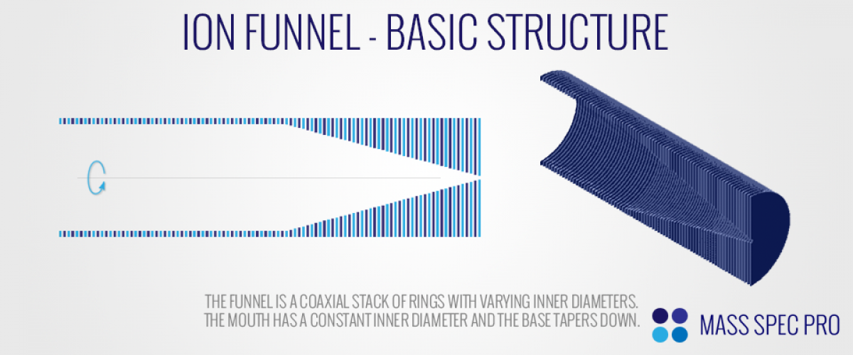
The ion funnel owes many of its characteristics to the "stacked ring ion guide" (SRIG). Even though the SRIG had been developed in the 1960's as an effective means to guiding ions, the concept of the ion funnel was not developed until the late 1990's. Researchers in Dick Smith's lab at Pacific Northwest National Labs (PNNL) modified the SRIG to make it better equipped for focusing beams down to small diameters. Like a SRIG, the ion funnel is comprised of a series of thin, coaxial disks aligned in a row. Whereas the disks of a SRIG have uniform inner diameters down the length of the guide, the disks of an ion funnel typically vary in diameter down its long axis. There is often a region at the mouth of the funnel in which the disks have uniform inner diameters, followed by a portion at the base of the funnel in which the inner diameters of the disks gradually taper down. The final plate of the funnel typically serves the purpose of conductance limit, sitting between the higher pressure first vacuum stage of an instrument and the lower pressure second vacuum stage.
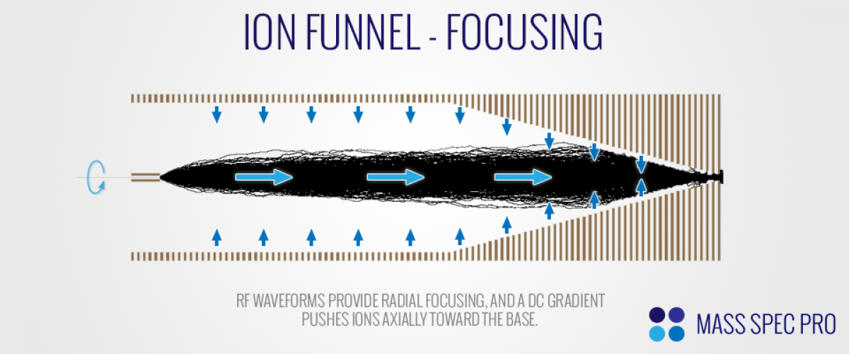
In order to operate effectively as an ion optical element, the funnel needs to push ions radially toward the centerline and push ions axially toward the narrow base. The radial force is provided via an "effective potential" from RF waveforms on the rings. As with the SRIG, the plates of an ion funnel are combined into two sets, alternating down the length of the funnel. One set of plates has an RF waveform applied to it (typically on the order of 100-200Vpp and ~700 kHz), and the second set of plates has an equal and opposite RF waveform applied to it, meaning it's perfectly 180 degrees out of phase with the other set of plates. When ions are relatively far away from the plates, the equal and opposite RF voltages essentially cancel out, providing little to no radial force. However, as an ion moves outward toward one of the plates it will start to feel a localized effect from said plate. When the plate is on its negative swing of an RF cycle, a positive ion is accelerated outward toward the plate. As the ion is beginning to move outward toward the plate, the RF voltage will begin to switch toward a positive voltage, accelerating the ion away from the plate and toward the center line. Since the ion had previously been accelerated outward, it is closer to the plate while experiencing the inward force. The closer proximity to the plate means that the inward force is stronger than the outward force. If we ignore the nuance of each individual RF cycle, and instead consider the average effect of the RF waveforms over time, the net result is an "effective potential" that pushes the ions radially inward. As with the SRIG, the effective potential is quite weak near the centerline of the funnel, but increases sharply near the plates. As such, ions can move rather freely in the radial dimension until they get very close to the plates where the effectively start to feel a strong inward radial force.
Even though the RF waveforms effectively keep ions off of the plates, they don't provide any push of the ions in the axial direction. With only RF applied, the ions would wander around the funnel's interior with little impetus to migrate towards the narrow end of the taper. In order to achieve an axial push, a DC gradient is applied to the rings (in addition to the aforementioned RF components). For positive ions, the frontmost plate at the mouth of the funnel is at the most positive DC voltage, and subsequent plates have gradually decreasing DC components. Positive ions will feel this DC gradient as a gradual "downhill" slope, pushing them towards the narrow base of the funnel. When combined, the RF and DC components of the ion funnel's electric fields provide excellent focusing of an ion beam, even when it is entrained in a rapidly expanding jet of gas.
Modifications to the Design
Numerous modifications have been made to the basic ion funnel design over its lifetime. In 2002, the concept of a "jet disrupter" was introduced. As with most atmsopheric interfaces, the ion funnel is prone to having fast neutrals and charged droplets shooting through the first vacuum stage and introducing noise when they strike electrodes further back in the instrument. It also faces the same problem of other optics, in that it should transmit the maximum number of ions (for sensitivity) and the minimum number of neutrals (for pumping). The jet disrupter tries to address these problems by placing a metal plate immediately in the line of sight of the gas stream as it enters the funnel. The electrode causes the incoming gas stream to spread radially as it flows around the obstruction. Any heavy neutrals or charged droplets slam into this electrode, this minimizing noise spikes. In addition to minimzing noise spikes, the diverging gas beam makes vacuum pumping easier, as it prevents the gas stream from having a clear path straight into the second vacuum stage. Lastly, since the funnel is well-adept at accepting a broad, divergent beam of ions with its electric fields, it is capable of pulling the ions out of these flow paths, negating most of the potential downsides of the modified flow. As such, the instrument is able to retain high sensitivity while minimizing noise and maximizing pumping. Other variations on this concept have been developed, including orthogonal injection of the ion beam into the funnel.
One particularly interesting variation on the ion funnel geometry, coined the "S-Lens", was patented by Thermo in 2010. The S-Lens concept takes advantage of the fact that when the interplate spacing of a ring stack is increased, the RF field penetrates further in radially (since the plates don't effectively cancel out as easily). As such, if the interplate spacing is increased, the radial focusing force will increase as well. The logical end result of this concept is a funnel in which the interelectrode spacing is gradually increased toward the base of the funnel rather than tapering down the inner diameters. As ions pass through the funnel, the increasing plate spacing causes increased radial forces; the ion beam is focused radially as it approaches the exit. The S-Lens geometry appears to be standard on all modern atmospheric interface designs for Thermo products.