Historical Background
In the late 1940's and early 1950's, two different research groups independently created the concept of "strong focusing" of charged particle beams. This new focusing approach utilized alternating electric fields and was able to make ion beams converge in two different dimensions. Previous focusing elements for ion beams utilized electrostatic fields. According to Earnshaw's theorem, electrostatic fields are incapable of focusing a beam in two dimensions. Thus "strong focusing" provided an intriguing path forward for guiding ion beams through instruments. This was also around the same time frame in which Wolfgang Paul and colleagues were developing the concept of quadrupole ions traps and quadrupole mass filters, both of which utilized alternating electric fields to confine/alter the trajectories of ions in interesting ways. Since these earliest days of development, ion guides have become nearly ubiquitous in modern mass spectrometers. Virtually every commercial atmsopheric pressure ionization instrument available on the market contains one or more ion guides to assist in the transport of ions through their vacuum chambers. They are an invaluable tool for instrument designers.
General Structure
Multipoles ion guides are generally created using metal rods of a certain cross-sectional shape arranged symmetrically around a central axis. The exact number and shape of the rods varies, depending on the desired use. The number of rods is virtually always even, with the most common numbers being 4, 6 and 8. The rod shapes are typically rectangular, round or hyperbolic. Here are a few examples:
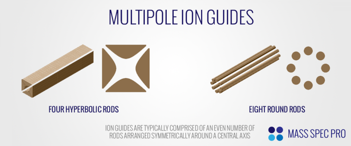
The number of rods is commonly referred to as the number of "poles" of the ion guide. As such, the common names for various numbers of rods/poles, are:
- Four rods: Quadrupole
- Six rods: Hexapole
- Eight rods: Octopole
- Ten rods: Decapole
- Twelve rods: Dodecapole
The "order" of a multipole guide, N, is obtained by dividing the number of poles by two:
- Four rods (Quadrupole), N=2
- Six rods (Hexapole), N=3
- Eight rods (Octopole), N=4
- Ten rods (Decapole), N=5
- Twelve rods (Dodecapole), N=6
The distance from the guide's center line to the nearest face of an electrode is commonly referred to as the "field radius" (r0). Typically, the length of the ion guide is much larger than its field radius.
Electric Fields
If we assume that an ion guide's rods are much longer than the field radius and are machined/aligned with high precision, then the electric field within the bulk of the ion guide's length will be uniform. In other words, no matter where the ions are located within the length of the guide, they will always feel the same electric field in the radial (xy) plane. As such, we typically represent the electric fields/potentials of ion guides in a two-dimensional format. For a multipole of order N, the potential in the xy plane is given by:
ΦN(x,y) = Re[(x+iy)N]/(r0N)
The potentials for the most common multipoles are:
- Quadrupole (N=2): Φ2(x,y) = (x2 + y2)/(r02)
- Hexapole (N=3): Φ3(x,y) = (x3 - 3xy2)/(r03)
- Octopole (N=4): Φ4(x,y) = (x4 - 6x2y2 + y4)/(r04)
- Decapole (N=5): Φ5(x,y) = (x5 - 10x3y2 + 5xy4)/(r05)
- Dodecapole (N=6): Φ6(x,y) = (x6 - 15x4y2 + 15x2y4 - y6)/(r06)
In order to generate these electric fields exactly, the ion guide electrodes would need to be hyperbolic and extend infinitely in the xy plane. However, it is more common for ion guides to have round or flat electrodes for ease of manufacturing. These "imperfect" shapes result in electric fields that are not exactly quadrupolar, hexapolar, octopolar, etc. Instead they result in fields that are some linear superposition of the various fields:
Φreal = A2Φ2(x,y) + A3Φ3(x,y) + A4Φ4(x,y) + A5Φ5(x,y) + A6Φ6(x,y) + ...
If it's of critical importance to have an electric field that precisely matches a specific multipole (e.g. "pure" octopole), nothing is better than hyperbolic electrodes. If that is not possible, a close approximation can be made through the use of round rods with precise diameters and positions. Having said that, there typically is no need to worry about such precision with ion guides, as they can focus ions quite well regardless of how closely they match a specific multipole field.
In order to generate a multipole potential, the set of rods is separated into two pairs, alternating as you go around the central axis such that each rod is neighbored by rods of the other pair. Once the rods are grouped into pairs, the first pair has a particular voltage applied to it, while the second pair has an equal voltage of the opposite polarity applied to it. Consider as an example an octopole ion guide comprised of eight round electrodes. The eight rods are grouped into two sets of four. Assume that the first set of rods has +100V applied to it while the second set of rods has -100V applied to it. Then the potential in the xy plane will look something like this:
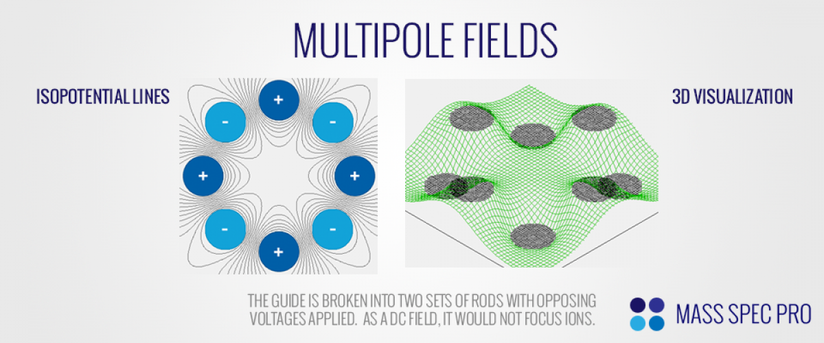
The octopole's equal and opposite voltages create an interesting potential distribution in the xy plane, with one set of rods (+) at an "uphill" potential to ions of positive polarity and the other set of rods (-) at a "downhill" potential to the same ions. Also note that the middle of the guide has a relatively "flat" potential, getting steeper as you approach the rods. As such, ions feel a stronger force from the multipole field when they are far from the centerline.
If these voltages were applied in a static fashion (viz. a DC field), ions would not be focused. Instead, positive ions would be pulled into the negative rods while negative ions were pulled into the positive rods. The focusing "magic" comes in when alternating voltages are applied to the rods. Instead of a fixed DC potential, an RF voltage is applied to one set of rods, while an equal and opposite phase RF voltage is applied to the other set of rods. At any instant in time, the field is accelerating ions toward one rod set. However, while the ions are starting to move toward the first rod set, the RF field quickly changes and starts accelerating ions toward the other rod set. If the speed at which the field changes (RF frequency) and the strength with which it pushes the ions (RF amplitude) are set appropriately, the ions will not hit either rod set, instead remaining focused down the length of the guide:
Even though the RF fields are oscillating rapidly with time, they can be mathematically modeled as an "effective mechanical potential", describing their time-averaged effect as a constant restoring force to the center of the guide. In other words, instead of focusing on the nuance of what's happening on the very fast time scale of each individual RF cycle, we can instead look at the overall effect that the RF fields have on a longer time scale. This effective mechanical potential is related to both radial position (r) and multipole order (N) by the following:
Ueff(r) ∝ r(2N-2)
The first thing to note about this effective potential is that it increases with radial position. In other words, when ions are further from the center line of a multipole they will feel a stronger effective potential pushing them back toward the center (r=0). Likewise, when ions are very near the center line of the multipole, they will experience very little radial force from the effective potential. The second thing to note about the effective potential is how the multipole order, N, affects its shape. The '2N-2' exponent means that lower order multipoles (e.g. quadupole, N=2) will exhibit a much more gradual increase in effective potential with increasing radius than a higher order multipole (e.g. octopole, N=8):
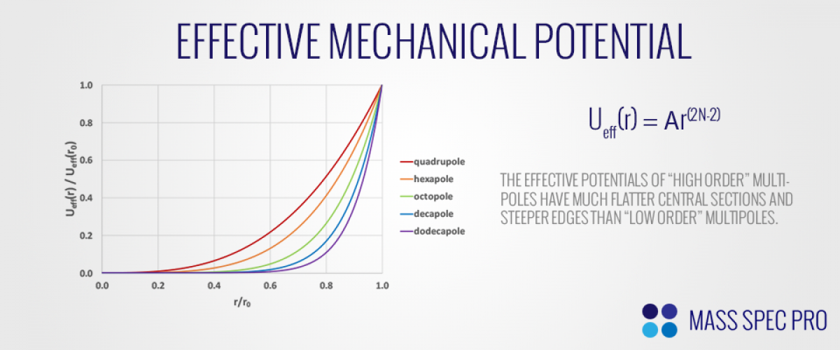
This "flatness" of the effective potential near the centerline turns out to be an important distinction between the various types of ion guides. Some higher order guides have very wide flat sections of their effective potentials, meaning that ions can occupy a larger fraction of the guide's radial dimensions before feeling significant force back toward the center. This can be advantageous for several reasons, namely (1) minimizing space charge forces since ions can spread out radially and (2) allowing for acceptance of a widely diverging beam. However, the wide flat portion of an ion guide's electric field can be detrimental at the guide's exit, where there is typically a conductance limit for a multistage vacuum system. From a pumping perspective it is ideal to keep this hole as small as possible. However, if the ion guide has a wide flat electric field at its center, it will be unable to focus the ion beam down to a small point, meaning many ions could be lost as they strike the walls of the conductance limit. In that situation there would have to be a compromise between (a) opening up the aperture to allow higher ion transmission but poorer pumping or (b) keeping the small aperture for efficient pumping but losing ions to the walls.
Collisional Focusing
While multipole ion guides are capable of focusing an ion beam in high vacuum, where ions experience virtually no collisions with neutrals, they are more typically operated in higher pressure regions of mass spectrometers, with pressures ranging form ~1 Torr down to ~1 mTorr. As such, the ions are regularly colliding with neutrals as they travel through the ion guide's electric fields. When ions undergo regular collisions, they gradually lose kinetic energy. The loss of kinetic energy makes it easier for the ion guide to focus the ion beam, causing the ion beam to decrease its radial extent. This process goes by several names, including "collisional cooling" and "thermalizing".
Bent Ion Guides
While conventional ion guides are straight, there are certain use cases in which it's beneficial to bend the guide. The most common example is minimizing line of sight between an atmospheric inlet and subsequent vacuum stages on atmospheric pressure ionization instruments. In these instruments, ions and charged droplets which are generated external to the instrument (at atmsopheric pressure) are pulled into the vacuum chamber's first "stage", where they undergo a free jet expansion. Heavy charged droplets within this expansion are of particular concern, because their momenutm can potentially carry them straight back into the vacuum chamber, where they can cause random noise spikes on the instrument's detector. This random noise can lead to poorer detection limits and sensitivity. Ideally the instrument would eliminate these undesired droplets while maintaining a beam of analyte ions. A bent ion guide provides this capability. For example, if a "square quadrupole" (aka "flatpole") is slowly bent around a turn, it is possible to effectively pass ions through the bend, while the heavy droplets (which are not well-controlled by the electric fields) strike the rods and are therefore not transmitted further through the instrument. Several academic papers have explored this concept, and numerous commercial instruments utilize this technique in some manner.
Recently, a bent ion guide known as the "C-Trap" has been developed specifically for injecting ions into the Orbitrap mass analyzer. The "C-Trap" is comprised of four flat rods that are bent around a curve. Ions are collisionally cooled/focused such that they are arranged around the bent centerline of the guide with quite low kinetic energies. The RF is then rapidly turned off, and DC voltages are applied to the rods, such that the ions are pushed through a slit in the inner electrode. If the geometry, voltages, timing, etc. are all set appropriately, the ions can be focused to a small point outside the C-Trap with an exceptionally narrow distribution of kinetic energies and arrival times; this is of ciritical importance for injecting ions into the Orbitrap.
Other Ion Guide Uses
Ion guides can be more than just "dumb pipes" for transporting ions through a vacuum system. For example, they can also be used to trap ions for some duration of time. If appropriate DC voltages are placed on plates at the entrance and exit of a guide while the RF waveforms confine the ions radially, then ions can be effectively trapped within the volume of the guide. This trapping capability can be utilized to study ion-molecule reaction kinetics or pre-concentrate an ion beam before injecting into a mass analyzer.